


_svg+%e6%8b%b7%e8%b2%9d.jpg)

- 10Hz-10MHz usable bandwidth
- Low loss design
- 5 Amps maximum current
- 50VDC max input
- Easily measure input filters and PSRR
Application Examples
- Techniques for accurate Power Supply Rejection Ratio (PSRR) measurements -Document
- PSRR measurement using the J2120A Line Injector -Forum
- PSRR measurement on a Bode 100 -Document -Youtube
- PSRR measurement on a Tektronix Scope -Youtube
- PSRR measurement on a 5/6 Se ries MSO Oscilloscope -Youtube
- PSRR measurement on an Oscill oscope (Tektronix) -Video
- Remote Sensing to Remove Non linear DC Drop -Document
- J2120A voltage drop and output resistance -Youtube
- How to confirm whether your J2120A is functioning properly? - Document1 Document2
Product Information
While the injection transformer is a very wideband adapter, it is not useful for measuring ripple rejection (PSRR) of a power supply or even an opamp. This is because the attributes that make the injection transformer perform so well also result in a transformer that is intolerant of DC current. Even very small DC currents (5mA or less) can greatly reduce the signal capacity or even totally saturate the transformer. For this reason, the Picotest line injector (J2120A) is another essential test adapter.
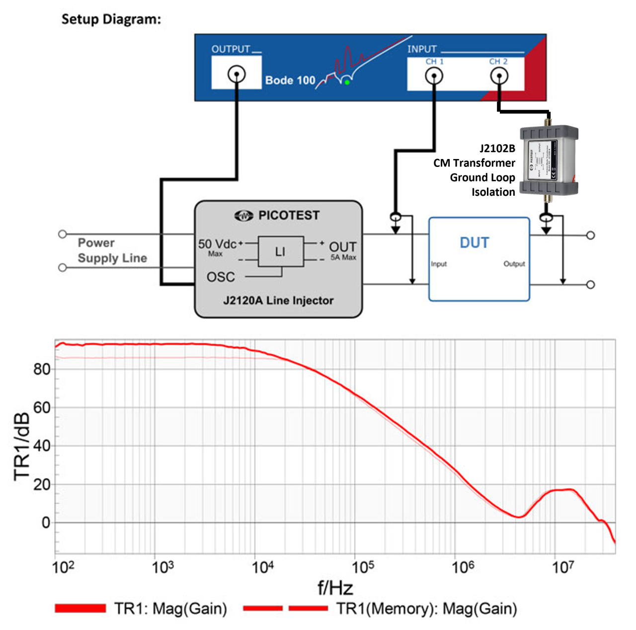
The line injector allows the input DC supply voltage to be modulated by the network analyzer source signal, as in the case of a PSRR measurement. The line injector must be capable of a frequency range well below the AC line frequency and at least above the control loop bandwidth of the circuit being tested.
The line injector is only capable of sourcing current, so that the output amplitude can be significantly impacted by the operating current and the total storage capacitance at the load. The network analyzer has a very high selectivity so distortion at the output of the line injector generally does not influence the measurement. Again, this is a small signal injector, so the oscillator signals should be kept as small as possible above the noise floor. As a guide, try to keep the input signal amplitude below 50mVpp (-20dBm). In some cases we want to attenuate the source signal even further, and so we have included the attenuators in the injector kits. Some analyzers, such as the Omicron-Lab-Lab Bode-100 allow shaping the injection amplitude as a function of frequency, which helps optimize the signal level.
 |
 |
Measuring Input Impedance
The line injector can also be used in conjunction with a current probe to measure the input impedance of a power supply. The input impedance of a switching power supply or regulator is negative, which is a stability concern when combined with an EMI filter, making the measurement an important part of the design, analysis and verification process. The current probe must be set for 1A/V or the results need to be scaled accordingly for different settings.
Detailed Specifications
| Specifications | |
| Characteristic | Typical |
| Maximum DC Input Voltage | 50VDC |
| Maximum Continuous Current | 5A |
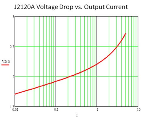
| Maximum Voltage Drop | 3.25VDC |
| Modulation Input Impedance | 10K ohms |
| 3dB Frequency Response | 15Hz ~ 5MHz |
| Useable Frequency Response | 10Hz ~ 10MHz |
| Recommended Injection Signal | -20 ~ 0dBm |
| Temperature Range | 0 ~ 50°C |
| Maximum Altitude | 6000 Ft |
| Absolute Maximum Voltage | < 50V (DC + AC) |
 |
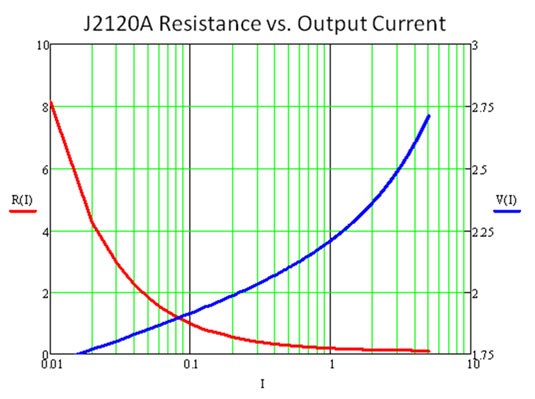 |
J2120A is the lowest impedance injector on the market and can be approximated by the following relationship to operating current.
Caution:To avoid equipment damage and/or severe injuries or death ensure that the absolute maximum ratings are observed and not exceeded at all times.
EMI Note:Exceeding 0dBm may cause the unit to exceed CE EMI limits.
What’s included
- J2120A Line Injector
- User manual
- 1 Year Warranty